The purpose of this guideline is to provide design and construction suggestions for Cleanrooms housing bio-pharmaceutical processes.
Table of Contents
Scope
The following suggestions are intended to assume that the facilities, when used properly, will meet the airborne Particulate Classes for Cleanrooms and Clean Zones, and will provide an environment that does not negatively affect bio-pharmaceutical processes conducted therein. Air cleanliness within the cleanroom suite may range from Class 100 through Class 100,000. In addition areas may be considered clean or labeled as "controlled environment" without having cleanliness class assigned to the space.
A cleanliness classification in accordance with the latest revision of Federal Standard 209 (see below) is generally inadequate by itself to describe a facility used for bio-pharmaceutical processes. The presence of viable particles (living organisms) within the particle count achieved by applying methods described in Federal Standard 209 may affect operations of the cleanroom. A measure of both viable and non-viable particles is required to provide sufficient information upon which to base a decision regarding the suitability of the cleanroom for its intended purpose.
The suggestion presented herein are intended to provide facilities that will effectively restrict both viable and non-viable particles from entering the cleanroom, minimize contamination introduced by the family itself, and continuously remove contaminants generated during normal operations.
Measurements of total particle count in the cleanroom is described in Federal Standard 209. This count may be composed of viable, non-viable, or non-viable host particles with a viable traveler. There is no generally accepted relationship between total particle count and viable particle count. While maintaining appropriate particle counts is important in design and operation, a protocol designed to identify viable particles should be inherent in the certification/validation testing of a pharmaceutical cleanroom.
No facility will compensate for excessive contamination generated within it. In addition to effectively facility design, the user must also institute a routine maintenance program as well as maintain personnel and operational disciplines that limit particles generated within the facility as well as entry of particles into the facility.
This design guideline only provides suggestions for contamination control in facility design. It must be implemented in accordance with all appropriate government and regulatory building and safety codes. The design guideline is nonspecific and regards biological or chemical materials that may be used within the facility. Good practice as well as any regulations governing biological and pharmaceutical processes conducted within the facility must be adhere to as required, and may modify some of the recommendations contained herein.
Cleanroom Design Considerations
Cleaning Classification - The classification of the cleanroom is determined by the using organization consistent with the level of non-viable and viable particulate contamination acceptable to the process conducted within the facility. This may be governed by regulatory agencies, client organizations, or company protocols. Target goals shall be set for non-viable particle count in accordance with Federal Standard 209. Viable particle target goals shall be stated in CFU/sq.cm (colony forming units/square centimeter). In accordance with Federal Standard 209, particle goals with typically be identified for "At Rest" and "Operational" modes.
|
ISO 14644-1 Cleanroom Standards |
|||||||
|
Class |
maximum particles / m3 |
FED STD 209E |
|||||
|
≥0.1 µm |
≥0.2 µm |
≥0.3 µm |
≥0.5 µm |
≥1 µm |
≥5 µm |
||
|
ISO 1 |
10 |
2.37 |
1.02 |
0.35 |
0.083 |
0.0029 |
|
|
ISO 2 |
100 |
23.7 |
10.2 |
3.5 |
0.83 |
0.029 |
|
|
ISO 3 |
1,000 |
237 |
102 |
35 |
8.3 |
0.29 |
Class 1 Cleanroom |
|
ISO 4 |
10,000 |
2,370 |
1,020 |
352 |
83 |
2.9 |
Class 10 Cleanroom |
|
ISO 5 |
100,000 |
23,700 |
10,200 |
3,520 |
832 |
29 |
Class 100 Cleanroom |
|
ISO 6 |
1.0×10⁶ |
237,000 |
102,000 |
35,200 |
8,320 |
293 |
Class 1,000 Cleanroom |
|
ISO 7 |
1.0×10⁷ |
2.37×10⁶ |
1,020,000 |
352,000 |
83,200 |
2,930 |
Class 10,000 Cleanroom |
|
ISO 8 |
1.0×10⁸ |
2.37×10⁷ |
1.02×10⁷ |
3,520,000 |
832,000 |
29,300 |
Class 100,000 Cleanroom |
|
ISO 9 |
1.0×10⁹ |
2.37×10⁸ |
1.02×10⁸ |
35,200,000 |
8,320,000 |
293,000 |
Room air |
Recommendations-In the absence of other guidance governing the cleanliness classification and acceptable levels of microbial contamination of the cleanroom, the values presented in Appendix A may be used. The room grades presented are from most critical (A.) to least critical (E.). The definition of criticality is left to the cleanroom user organization.
Facility design
Design parameters that support the process within the cleanroom should be established by the user organization. Parameters such as temperature and humidity may be process driven or comfort driven, and therefore selected to accommodate specific comfort or process requirements as determined by the end user.
Local control
Under some circumstances, cleanliness requirements can be achieved through the use of localized controls such as clean tents, glove boxes or isolators. These provide unidirectional filtered airflow within a limited area. They may be located within a facility that provides the necessary temperature and humidity conditions or they may be provided with integral environmental control equipment designed to maintain necessary conditions.
Air change Rate
The airflow pattern and air change rate in a cleanroom largely determines the class of cleanliness that can be maintained during a given operation. Non-unidirectional flow cleanrooms rely on air dilution as will as a general ceiling to floor airflow pattern to continuously remove contaminants generated within the room. Unidirectional flow is more effective in continuously sweeping particles from the air due to the piston effect created by the uniform air velocity. The desired air change rate is determined based on the cleanliness class of the room and the density of operations expected in the room. An air change rate of 10-25 per hour is common for a large, low density Class 100,000 (M6.5) cleanroom. Class 10,000 (M5.5 cleanrooms typically require 40-60 air changes per hour. In unidirectional flow cleanrooms, the air change rate is generally not used as the measure of airflow but rather the average cleanroom air velocity is the specified criterion. The average velocity in a typical Class 100 (M3.5) cleanroom will be 70-90 feet per minute. A tolerance of plus or minus 20% of design airflow is usually acceptable in the cleanroom.
Pressurization
A pressure differential should be maintained between adjacent areas, with the cleaner area having the higher pressure. This will prevent infiltration of external contamination through leaks and during the opening and closing of personnel doors. A minimum overpressure between clean areas of 5 Pa (.02 inches of water column (in. W.C.")) is recommended. The pressure between a clean area and adjacent unclean area should be 12-14 Pa (.05 in. W. C.). Where several cleanrooms of varying levels of cleanliness are joined as one complex, a positive pressure hierarchy of cleanliness levels should be maintained, including airlocks and gowning rooms. Note that for certain process it may be desirable to have a negative pressure relative to surrounding ambient in one or more rooms when containment is a major concern. A "room-with-in-a-room" may have to be designed to achieve this negative pressure yet still meet the needs of clean operation.
Temperature Control
Where occupant comfort is the main concern a temperature of 68-70 F+- 2 F will usually provide a comfortable environment for people wearing a typical lab coat. Where a full "bunny suit" or protective attire is to be worn room temperature as low as 66 F may be required. If the temperature is to be controlled in response to process concerns the value and tolerance should be specified early in the design phase to insure that budgeting is accurate.
Humidity Control
Humidity requirements for comfort are in the range of 30-60%RH. If process concerns suggest another value it should be specified as soon as possible in the design process. Bio-pharmaceutical materials sensitive to humidity variations or excessively high or low values may require stringent controls.
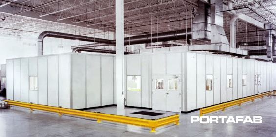
Facility Layout
The facility layout should support the process contained within the cleanroom. While a rectangular shape is easiest to accommodate, other shapes may be incorporated into the facility as long as appropriate attention is paid to airflow patterns. The facility should be able to accommodate movement of equipment, material and personnel into and out of the cleanroom. The layout of the clean suite should facilitate maintaining cleanliness class, pressure differentials, and temperature/humidity conditions by isolating critical spaces and by excluding non-clean operations.
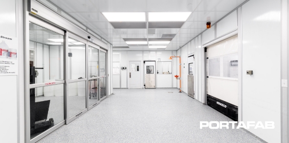
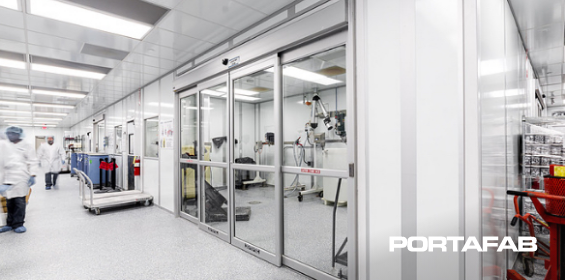
Cleanroom airlock (also known as an AnteRoom)
Airlocks or AnteRoom
This is a room between the cleanroom and an un-rated or less clean area surrounding the cleanroom or between two rooms of differing cleanliness class. The purpose of the room is to maintain pressurization differentials between spaces of different cleanliness class. An airlock can serve as a gowning area. Certain airlocks may be designated as an equipment or material airlock and provide a space to remove packaging materials and/or clean equipment or materials before they are introduced into the cleanroom. Interlocks are recommended for airlock door sets to prevent opening of both doors simultaneously. For equipment airlocks, an indicator light inside the cleanrooms in recommended to show when the outside door is open.
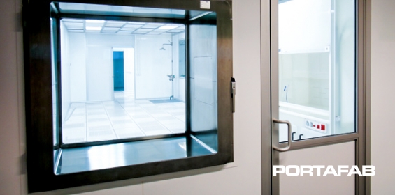
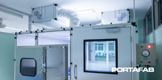
Cleanroom designed with a pass-through window.
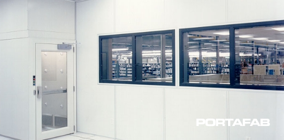
Windows
Windows are recommended in cleanrooms to facilitate supervision and for safety, unless prohibited by the facility protocol for security reasons. Windows should be placed to permit viewing of operations in order to minimize the need for non-cleanroom personnel to enter the cleanroom. Windows should be impact resistant glass or acrylic, fully glazed, installed in a manner that eliminates or minimizes a ledge within the clean space. Double-glazing is frequently used to provide a flush surface on both sides of the wall containing the window. Windows may be included if there is a public relations requirement for visitors to view the operations. Speaking diaphragms of flush, wall mounted, intercom systems are recommended near all windows to facilitate communication with occupants of the cleanroom.
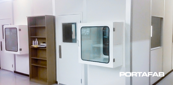
Pass-Throughs
A pass-through airlock should be provided for the transfer of small articles from uncontrolled areas into the cleanroom or between areas of different cleanliness class. The pass-through may include a speaking diaphragm, intercom, or telephone for communication when items are transferred, and interlocks to prevent both doors from being opened at the same time. A cart size pass-through installed at floor level can be used to facilitate movement of carts between clean areas. Stainless steel is typically the material of choice.
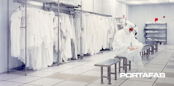
Gowning Rooms
Should be designed to support the garment protocol established for the facility. A typical gowning room may have the following items:
- Wall mounted coat rack for clean garment storage located at a height to prevent dragging on the floor.
- Bench A full-length mirror installed near the door for gowning self-inspection. Storage for packaged garments
- Bins for disposal of soiled garments.
Personal lockers and coat racks for the storage of notebooks, coats, and personal items should be located outside gowning room or in an antechamber separate from the clean room or in an antechamber adjacent to the clean gowning area. A common gowning room design has two areas divided by a bench. The "unclean" area is used to remove and store outer garments. Stepping over the bench, as the cleanroom footwear is being put on insures that the "clean" side of the gowning room will remain that way. Final donning of the cleanroom garb is then accomplished.
Siting
A cleanroom that serves as part of a larger process line should be integrated into the line to facilitate movement of personnel and materials in and out of the room. A free-standing cleanroon may be located in any convenient site however certain conditions adjacent to the facility may degrade its performance. Vibration sources inside or near a cleanroom will encourage particle release within the room and under severe conditions may cause leaks in filters and ductwork. Heavy equipment including the HVAC systems components, pumps, house vacuum system, etc ought to be vibration isolated. Location of a cleanroom directly adjacent to heavy equipment or loading docks that see heavy truck traffic, and other sources of vibration, shock and noise may be problematic. The outdoor air intake for the cleanroom makeup air must be carefully located to prevent overloading of filters or entrance of contaminating gases that the filter will not remove. Cleanroom air intakes should not be located near loading docks, traffic lanes, or other areas where vehicles may drive through or idle. These intakes should not be located near the exhaust locations of other processing facilities. Use of gas phase filtration may be required if the quality of make-up air is not acceptable.
Walls
Basic steel stud construction with gypsum board paneling is commonly used bio-pharmaceutical cleanrooms when appropriately coated with a non-shedding finish. Modular wall systems utilizing coated steel or aluminum panel construction are growing in popularity due to the ability to easily retrofit a lab or production space at a later date with minimal disruption due to construction developed that address the concerns of the bio-pharmaceutical cleanroom user relative to surface finish integrity and smooth surfaces. Concrete block construction is also used when finished with an epoxy or other smooth coating. Rounded, easy to clean corners, should be a feature of any wall systems design, whether modular or "stick-built"..
Wall Finishes
Inexpensive latex wall paints will powder over time and are unacceptable in cleanrooms. Acceptable wall finishes include epoxy pain, polyurethane, or baked enamel, of a semi-gloss or gloss type. These may be applied in the factory to metal wall systems panels. Field application of epoxy to gypsum board or concrete block should be done to insure a smooth, non-porous, monolithic surface that will not provide a breeding site for organisms. Exposed corners is high traffic areas as well as on lower wall surfaces may have stainless steel facings or guards to prevent impact damage to the wall. This is particularly true when gypsum board construction is used. Corner and wall guards should extent from the floor to at least the 4 foot height. Traditionally the cleanroom has been white throughout as an indication of the clean nature of the facility and to identify it as a special work space. Other colors may be used in the cleanroom to provide an interesting environment as long as t he materials of construction do not contribute particles to the air stream and will withstand the sanitizing agents used in the facility..
Doors
Entry should be through airlocks to maintain cleanroom pressure differentials. Emergency exit doors should incorporate crash-bar mechanisms (or a similar emergency opening mechanism) with alarms for exit only. Emergency exit doors must be locked to exclude entry from the outside yet permit exiting from within. All doors should include essentially air-tight seals. Neoprene seals are generally acceptable. Brush-type door seal are not recommended. Foam rubber doors seals are not recommended as these have been found to quickly deteriorate and shed particles. All personnel doors and swinging equipment doors should include self-closing mechanisms. Manual and automatic sliding doors may be useful when space is an issue or to facilitate movement between spaces of similar cleanliness class for personnel whose hands are otherwise engaged. As the mechanism of such doors can generate particulate a design specifically intended for cleanroom application should be selected.
Ceilings
Ceiling finish should be similar to that used on the walls. The requirements for sanitizing typically address the ceiling as well as the walls and ceiling material and finish selection should reflect this. Suspended ceilings using inverted "T" grid and lay-in panels may have a place in that part of the cleanroom suite not subjected to the rigors of regular sanitizing and where the possibility of trapped spaces to support organism growth is not considered an issue. When suspended panel ceilings are used the panels must be clipped or sealed in place to prevent movement due to air pressure changes. Modular wall systems designed of similar material and finish that should be considered. A feature of the cleanroom ceiling and walls should be a feature of the cleanroom ceiling design. This design permits incorporation of filtration and lighting into what is essentially a monolithic ceiling.
Floors
Commonly used floor finishes for bio-pharmaceutical cleanrooms include sheet vinyl installed using heat welded or chemically fused seams to provide an essentially seamless surface. Troweled epoxy and epoxy paint have also found wide use. Compatibility of the floor material with solvents, chemicals cleaning agents to be used in the room must be considered. A minimum 4" cove at the junction of floor and walls is recommended to facilitate cleaning. Modular wall systems have a recess that permits an essentially seamless junction between floor and wall. When a "stick-built" approach is used care should be taken to design cleanable intersections of walls and floors.
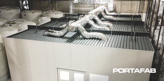
Airside
The cleanroom HVAC systems must be designed to maintain the required particulate cleanliness, temperature, humidity, and positive pressure at the expected outside environmental extremes and during the worst case expected use operations. Rapid recovery from upset conditions such as door openings and contaminate generating events is also a consideration. The high cost of conditioning outside air suggests that as much air as possible be recirculated. Recirculated air should be HEPA filtered in those spaces requiring a cleanliness classification in accordance with Federal Standard 209. Air that may be hazardous to health, even after HEPA filtration, should be exhausted after appropriate treatment. The required quantity of makeup air is calculated based on process exhaust plus air leakage from the cleanroom. A rate of two air changes per hour for cleanroom pressurization may be used in the absence of a more detailed calculation of air leakage. Make-up air should be drawn from the ou tdoors, conditioned and filtered as necessary before being introduced into the cleanroom recirculation air stream. Care should be taken to insure that make-up air intakes are not drawing in contaminated air.
Filtration
The filtration systems for a bio-pharmaceutical cleanroom typically consists of several stages of filters. Prefilters are selected, sized, and installed to maximize the life of the final HEPA filters. With proper selection of prefilters, the final HEPA filters should not require replacement within the life of the filter media and seal materials, a period of several years (perhaps as long as 10-15 years.
Make-up air is commonly filtered by a low efficiency (30% ASHRAE) prefilter followed by an intermediate (60% ASHARE) or high efficiency (95% ASHRAE) final filter. A screen should be included at the makeup air inlet to keep out pests and large debris. The make-up air is then directed to the recirculating air handler which also may have a low efficiency prefilter, although prefiltration of recirculated cleanroom air is often omitted because of its' high cleanliness level even after having passed through the cleanroom. The air is then directed through HEPA filters into the cleanroo m.High Efficiency Particulate Air (HEPA) filters must be a minimum of 99.97% efficient on 0.3 micron particles in accordance with Mil-F-51068 or IEST-RP-CC-001. Note that the filtration systems for an un-rated "controlled area" is the same, expect that the HEPA filter stage may be omitted.
Filter Location
HEPA filters may be installed in a facility either within an air handler or at the inlet to a plenum above the cleanroom or in the cleanroom ceiling. High velocity HEPA filters, that is, filters with a face velocity up to 500 feet per minute, are frequently installed in air handlers serving Class 100000 cleanrooms. Refer to Figure C. During the design phase care should be taken to provide access to both the upstream and downstream face of these filters to permit periodic challenging and leak testing. To provide HEPA filtered air over a limited area, within a larger controlled space, a ceiling mounted plenum may be used. This plenum has an air distribution means at its lower face that permits air to be introduced in a unidirectional manner over the critical process area. Refer to Figure D. HEPA filters are installed at the upper face of the plenum and the plenum is pressurized with filtered air. The ceiling mounted HEPA filters have a face velocity up to 100-120 feet per m inute.This is somewhat higher than the HEPA filters serving the rest of the cleanroom. The filters are commonly supplied with air by a duct distribution network consisting of rectangular or round trunk ducts and flexible or rigid round branch ducts. Full coverage, typical for Class 100 cleanrooms, or partial coverage, for higher class (less stringent) cleanrooms, can be accomplished using 2'x 4' lay-in HEPA filter modules installed in the ceiling.
Cleanroom Testing
Federal Standard 209 describes methodology and instrumentation for particle counting in the cleanroom. The tests described there are the basis for assigning a cleanliness rating to the facility. IEST-RP-CC-006 similarly provides a procedure for particle counting but goes beyond that to a full series of tests that can be conducted to determine the effectiveness of the cleanroom and it's operability. The determination of which tests should be run is up to the cleanroom end user. As a minimum particle counting, room pressurization and filter leakage tests should be run. Other test dealing with airflow pattern, temperature, humidity, lighting and sound levels are available.
Once acceptance test has been conducted an ongoing periodic monitoring program should be initiated to insure that cleanroom performance degradation is identified as it occurs. Pass-fail criteria are not part of the standard, but are to be developed on a case by case basis by the end user of the facility.
Utilities
Bio-pharmaceutical cleanrooms typically house process equipment requiring utilities such as pure water, electricity, vacuum, clean compressed air, etc. The source of these utilities to the point of use care should be taken to insure that the cleanroom is not compromised. A clean construction protocol should be implemented and wall, ceiling, and floor penetration, if needed, should be flashed and sealed in such a manner as to prevent particles form entering the cleanroom. Such entry points should also be smoothly sealed to insure that there are no crevices to harbor organisms. Drains should be avoided in the cleanroom wherever possible. When this is not possible the drains should be covered when not in use with a means specifically designed for bio-pharmaceutical cleanroom application. Such means are tight, smooth, cleanable, and corrosion resistant.
Receive an Immediate Price Quote
Interested in a custom price quote for a cleanroom or environmental enclosure? Click below to submit your inquiry to one of our cleanroom sales managers and they will respond quickly to your inquiry.